A mobile, PXI-based proof-of-concept system achieves flexible operation across pulsed and CW modes successfully tested on the SWELL cavity in SM18.
At CERN, the SRF team is responsible for characterizing superconducting RF cavities through extensive testing under realistic operational conditions. Their work is essential for providing insights into cavity performance, refining design parameters, and identifying performance limits for superconducting cavities.
To support these efforts, a digital Self-Excited Loop (SEL) system has been developed on PXI hardware by the MTA section. This LabVIEW-based proof-of-concept system integrates FPGA-controlled signal generation and acquisition within a flexible, modular design. In general, SEL systems are effective for characterizing high-Q₀ cavities by providing stable feedback loops and compensating for instabilities.
The system was initially validated with a non-superconducting 1.3 GHz cavity to demonstrate loop stability and verify FPGA resource usage and signal control. Following this, the system was deployed for testing at SM18 with the SWELL superconducting cavity on the V5 test stand. The cavity was tested under cryogenic conditions and benchmarked against CERN’s VME-based SEL system. This comparison served to fact-check the acquired data and showed strong potential for the PXI-based approach.
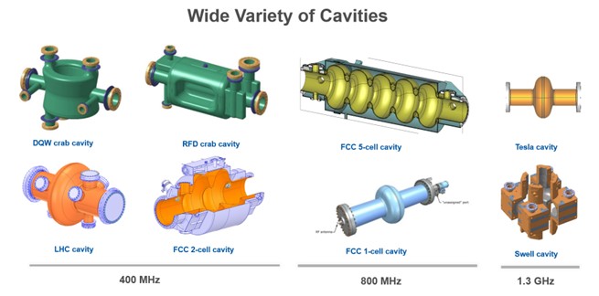
Developed in close collaboration with the SRF team, the system is designed to support ongoing superconducting cavity characterization with a mobile system able to test a wide variety of cavities, which operate at different resonance frequencies.
System Overview
SEL systems are well-suited for high-Q₀ superconducting cavities as they can track and compensate for instabilities caused by thermal noise, mechanical detuning, and microphonics, which can cause resonance shifts. These instabilities are especially critical to monitor, as they can disrupt the phase alignment needed for sustained oscillation. When this happens, the system can fail to properly excite the cavity, effectively interrupting testing.
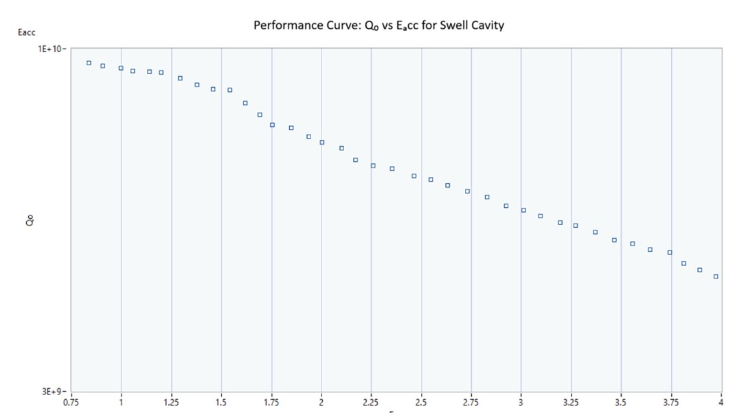
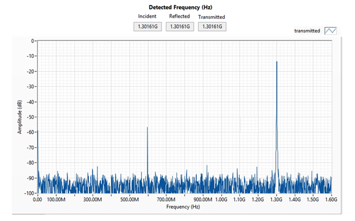
The PXI system generates the signal that drives the cavity and reads three key RF signals: forward, reflected, and transmitted power. These signals are used to calculate key cavity parameters such as the loaded quality factor (Q₀) and to plot the performance curve relating accelerating gradient (Eₐᵤₜ) to Q₀. This Q vs Eₐᵤₜ curve helps assess cavity behaviour, identify operational limits, and detect possible fabrication or surface treatment defects.
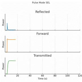
The system incorporates built-in phase scanning to automatically initiate oscillation and can operate in both continuous wave (CW) and pulsed modes. These modes are fully configurable, providing flexibility to accommodate various testing needs, types of cavities and experimental setups.
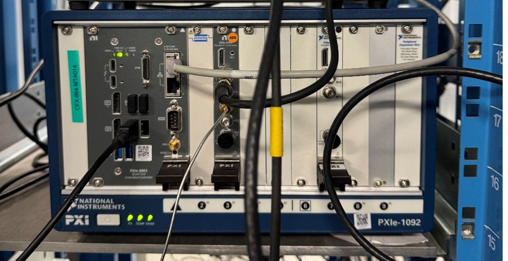
Using the PXIe-1082 chassis, the system uses PXIe-5775 and PXIe-5785 FPGA/digitizer cards, with LabVIEW-based control for real-time amplitude and phase loop regulation. It offers 12-bit acquisition of RF signals, including forward, reflected, and transmitted power. All measurement data is streamed into TDMS files with maximum frequency of 3.2GHz, with plans for future export capabilities in HDF5.
Toward a Unified and Expandable Testing Platform
One of the key advantages of the system is that it doesn't rely on downsampling or frequency downconversion. RF signals are acquired directly at the resonant frequency. This also allows for direct spectral analysis using FFT.
This also enables future possibilities for time-aligned correlation of quench events with diagnostics such as OSTs, X-ray sensors, or even emerging tools like acoustic or microphone-based monitoring, offering potential insights into the causes of performance-limiting phenomena.
The modular PXI architecture enables seamless integration with CERN’s existing PLL-based characterization systems. This flexibility opens the door to unifying PLL and SEL functionalities within a single platform, simplifying setup and operation for testing.
In addition to RF signals, the system architecture allows for easy expansion to include other diagnostics such as temperature, liquid helium level, pressure in the cavity volume and helium bath, magnetic probes, OST-based quench detection, dark current, and X-ray sensors. These additions could enhance the system’s ability to identify and correlate performance-limiting phenomena.