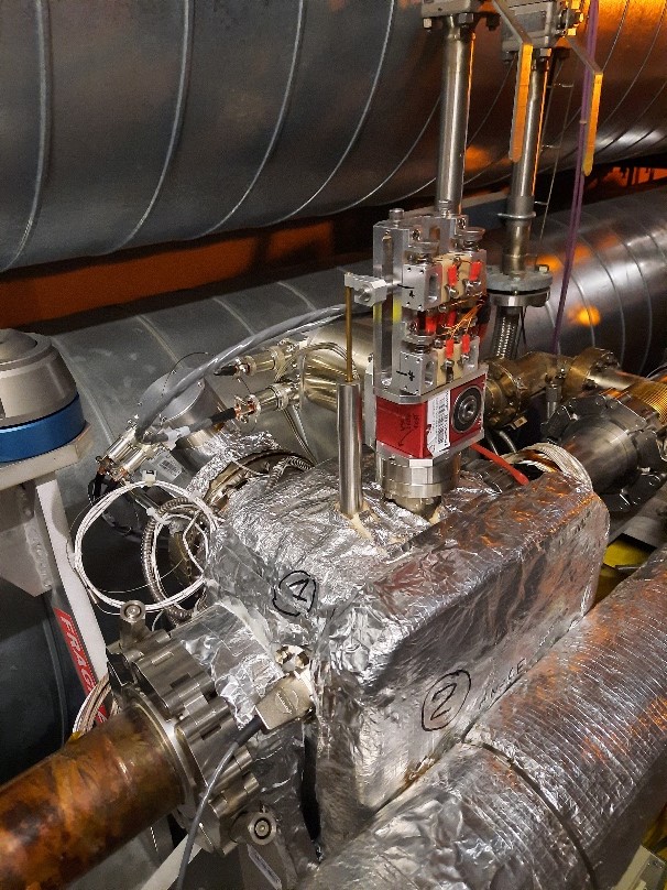
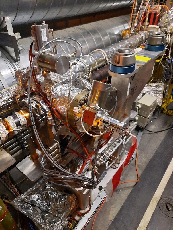
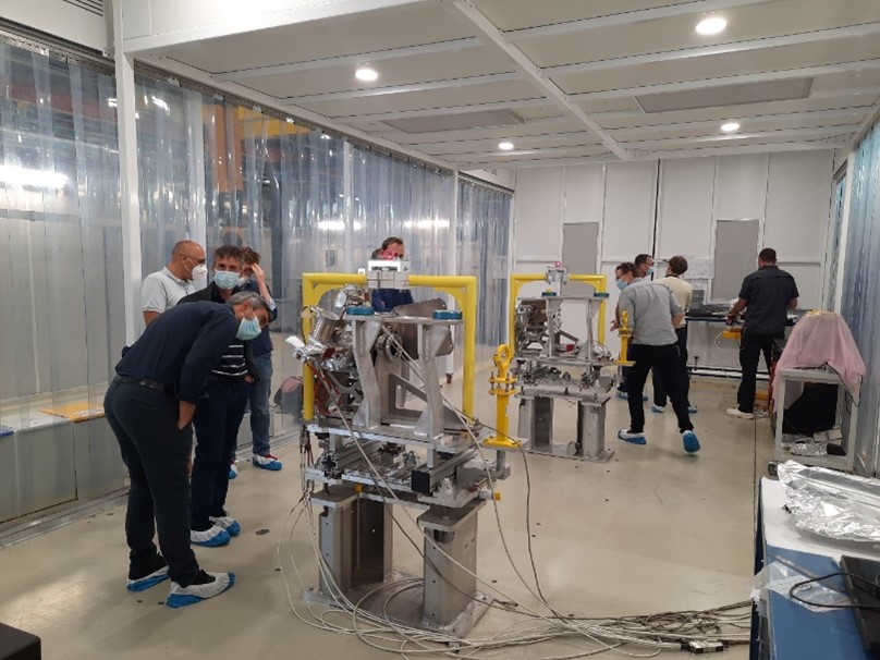
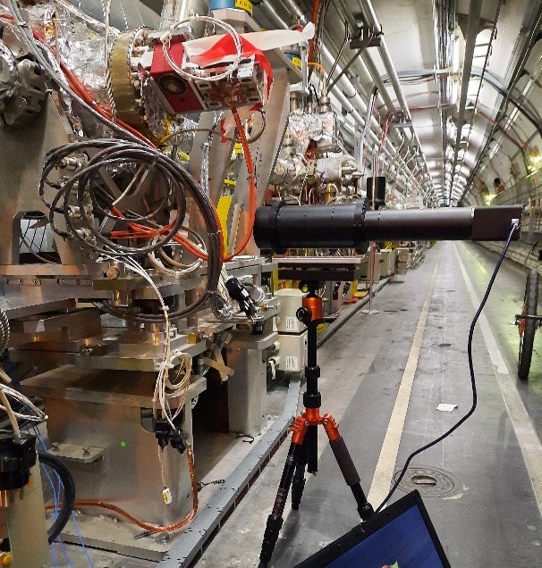
Piezo-goniometers are used in the LHC for crystal collimation and are critical for the HL-LHC upgrade. This technique uses bent crystals to deflect halo particles from ion beams, and to improve the cleaning performance. Currently four devices are installed in the LHC and have been under test since 2013 in Machine Development runs. During the year-end technical stop (YETS) in 2021, after an intense design and production phase in collaboration with SY-STI, two new devices have been installed to replace older and earlier models of the piezo-goniometers, and four more devices will be built in 2022. This year the devices will be in operation during the LHC ion runs. Each device consists of a high positioning performance rotational stage for the angular motion of the crystal at micro-radian scale, a linear stage to move the crystal in and out of the beam, and a beam pipe that moves into the beam outside of MD runs, so that the device is transparent to the beam line.
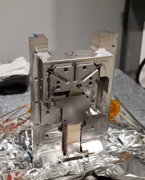
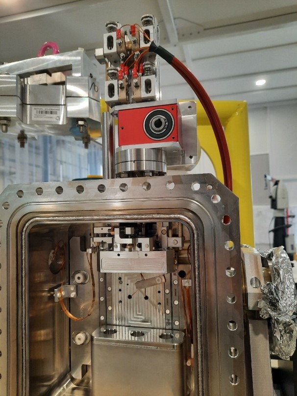
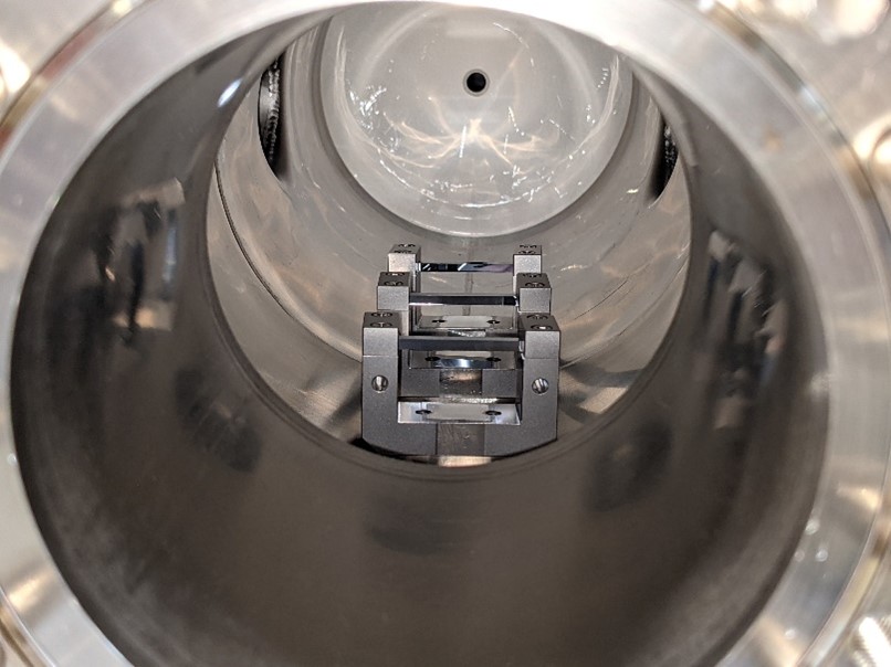
BE-CEM is responsible for the controls of the devices, as well as the characterization and alignment of the crystals, according to the specifications below. The linear stage and beam pipe are moved by stepper motors: the beam pipe via a standard driver and the linear stage via our inhouse designed driver that allows for closed loop Field Oriented Control mode. This is necessary to ensure that the vibrations caused by the stepper motor are minimised on the crystal surface. The rotational motion of the crystal is achieved via a custom piezo stack from CTS Corporation (previously Noliac) integrated into a rotational stage by Mecartex SA, with closed loop positional feedback provided by optical interferometry. A recent feature of the newly installed devices is that the interferometer heads are located outside the vacuum (by means of viewports) so that any fibre degradation due to motion or radiation can be fixed during routine maintenance.
| Property | Specification |
|---|---|
| Linear stroke | > 50mm |
| Linear resolution | 5 um |
| Linear accuracy | +/- 20 um |
| Total angular range | +/- 10 mrad |
| Yaw angular resolution | 0.1 urad |
| Yaw angular accuracy over the entire linear range | +/- 1 urad |
| Linear stroke | > 50mm |
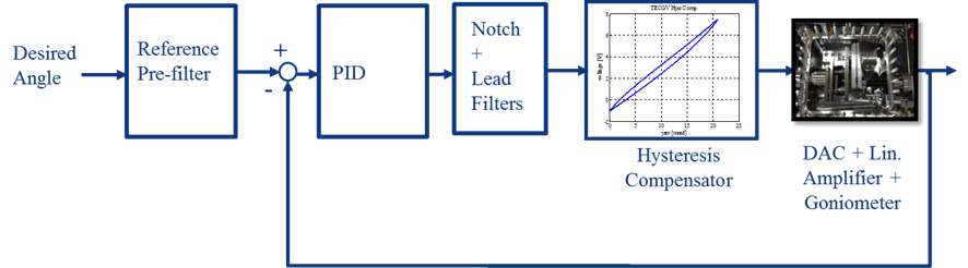
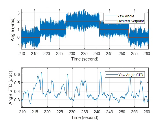
The yaw angular accuracy is achieved with our control algorithm that uses closed loop position control. Actuation of the crystal rotation is via the piezo-stack, powered by a low noise, high voltage linear amplifier with feedback from the three interferometer heads.
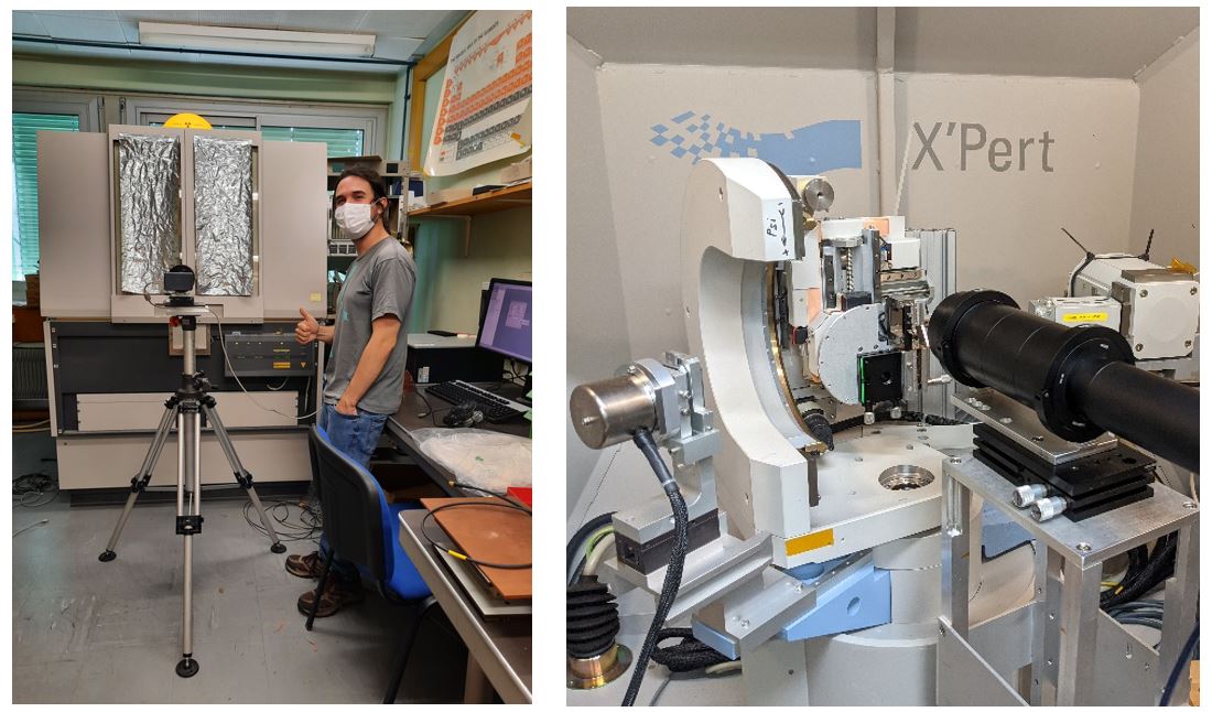
Many key milestones have been achieved in the last year – the characterisation of 10 crystals with the final choice of 2 determined by an H8 beam run, the installation and alignment of the crystals in the devices before and after leak tests and bake-out procedures and the controller parameterisation and optimisation. To characterise the crystals, we measure their bending, torsion and miscut parameters of the crystal lattice using x-ray diffractometry and the EN-EP X-Pert Panalytical Machine. These tests are carried out before and after thermal cycling, to ensure the long-term stability of the crystal performance.
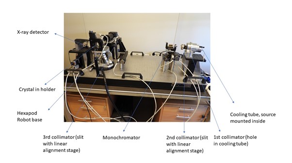
BE-CEM is developing a in house x-ray measurement machine that will allow for the precise alignment and measurements of crystals with differing sizes, with minimal parasitic angles in the device due to the choice of a hexapod actuator for the crystal pose control and the ability for a high level of automation during measurements.
A measure of the crystal efficiency to channel the beam and supporting measurements of bending and miscut are also determined via beam testing during H8 beam test runs. The alignment of the crystals with respect to the interferometer heads, and to the device tank, is carried out using an autocollimator during device construction, and at each stage of the installation to make sure any motion due to transport or other fluctuations is compensated for. During operation, the devices are put into closed loop control mode by the BE-CEM experts, before being handed over to OP who can then accurately position the crystal to ensure maximum channelling of the halo during the ion runs. We look forward to using these operational devices during Run 3 and further optimizing their performance.