Based on our wide-ranging expertise in robotics design and prototypes, we developed the Automated Robotic Inspection System (ARIS), which autonomously meets the needs of the SY-RF group at CERN to visually inspect the entire inner surface of radiofrequency (RF) cavities in LHC, Linac and FCC, and to detect any anomalies at short distance. So far, no commercial and custom systems on the market have addressed both issues.
This system is equipped with a liquid lens able to overcome depth of field (DOF) limitations, a high-resolution camera which ensures excellent quality photos regardless of the distance within the entire cavity, and an anticollision mechanism that can immediately stop the inspection system, if required. Furthermore, the final user of ARIS will be able to perform three different scan modes in three different cavity types through a user interface currently in development. This system is controlled using the CERN Robotic Framework - a robust software framework that is modular and used on all inhouse robotic platforms.
Inspection system requirements and challenges
The Automated Robotic Inspection System (ARIS) needed to fulfil the following criteria to perform the fully RF cavity inner surface inspection:
- Scan the LHC, LINAC and FCC cavities
- Scan 100% of each cavity
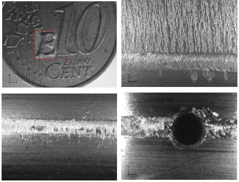
- Take photos of less than 2 cm square of the surface
- Take photos which should have between 30-50% of overlap
- Reach again any inner cavity surface position, where photos were previously taken
- Never collide the cavity with the arm
- Retract the arm safely, without colliding with the cavity
Regarding the vision system, the main challenge was to perform a full scan, by ensuring the overlap percentage. For this purpose, we implemented an iteration of the process which consists of driving the robotic arm to reach the next desired pre-computed position and to stop there. At this step, an auto-focus verification is performed, followed by the streamed image acquisition as the cavity is rotated through one full turn, at a speed compatible with real-time image capture and image overlap constraints. This process is then repeated for each position, thereby establishing a full-cavity scan.
From the mechanical design perspective, two main challenges were identified. Firstly, it was necessary to design an arm fitting the entrance diameter of the smallest cavity - less than 20 cm – and which could be deployed to reach the highest point of the largest cavity – in LHC – without collinding any of the three cavities. In addition to the complexity of the system components, each arm segment had to be optimized. The other challenge was the position of the motors, which were placed outside the cavity to reduce as much as possible the position error at the tip of the arm.
Mechanical design description of ARIS
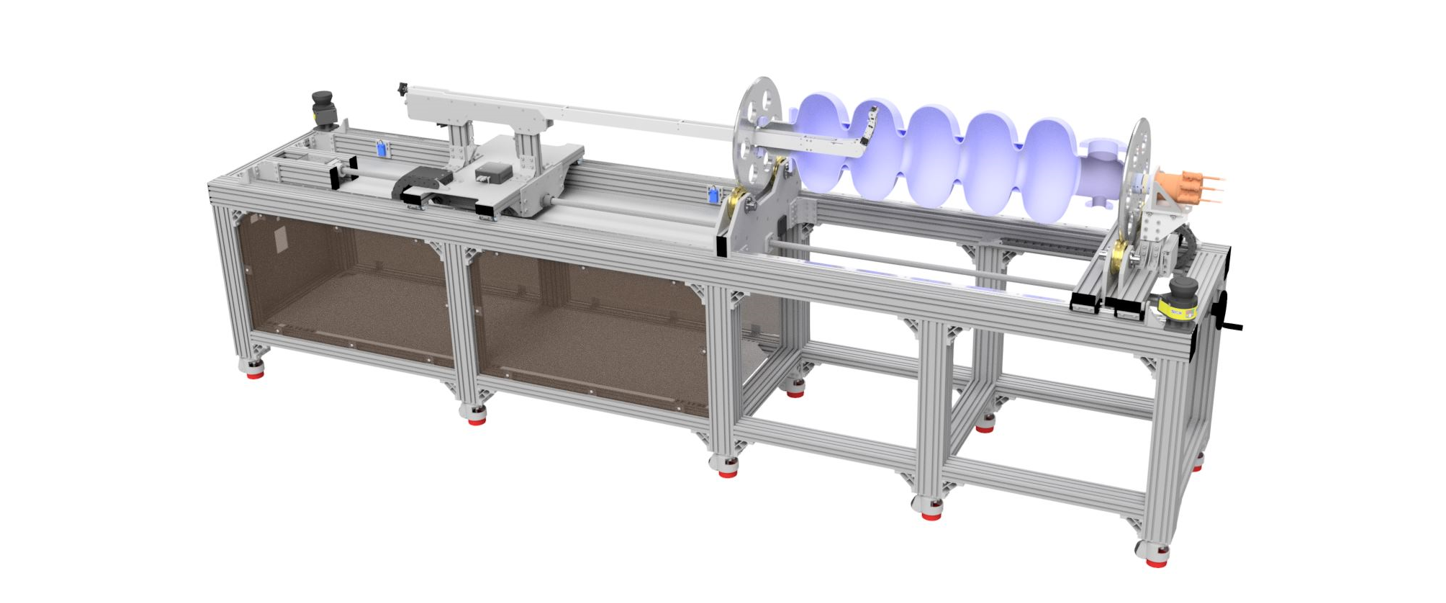
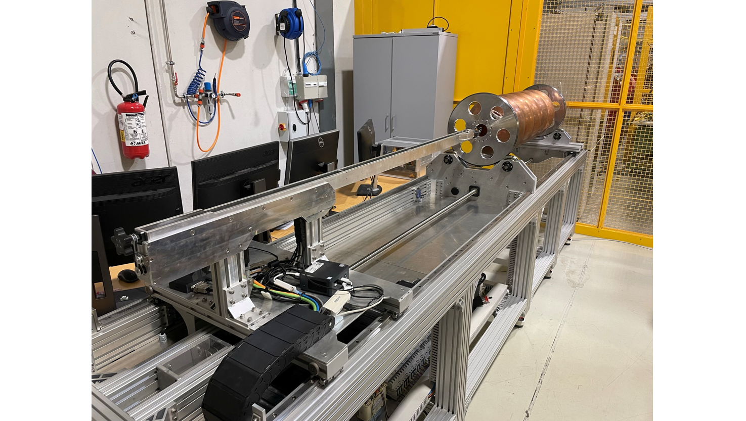
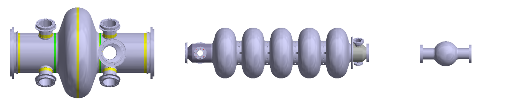
The Automated Robotic Inspection System (ARIS) is able to inspect three different cavities (from left to right hereafter: LHC, LINAC and FCC):
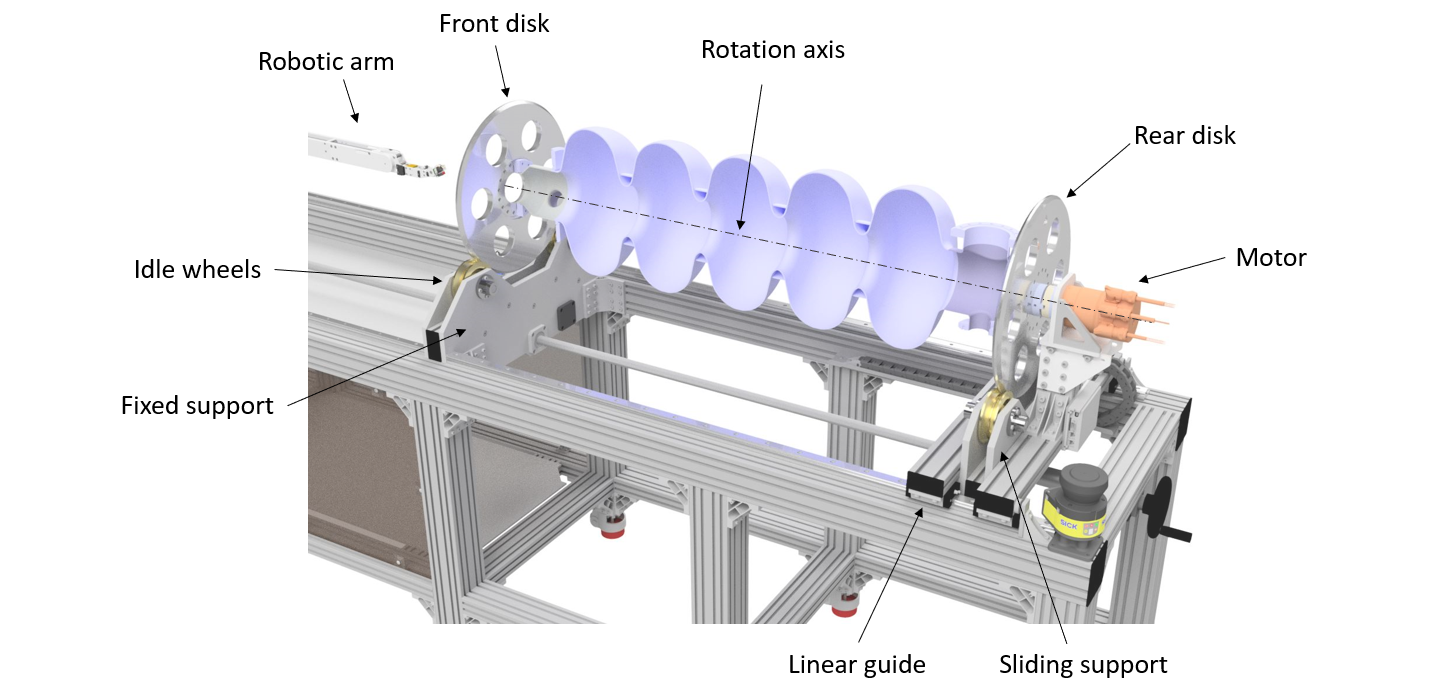
Cavity rotation
Each cavity is placed on the bench, by using two support discs screwed to the external flanges. The front disk (arm side) rotates on a fixed support system with idle wheels. The rear one is driven by a backlash free absolute harmonic drive-based motor with an absolute encoder, and rotates on a sliding support. This allows the bench to be adapted to the three different cavity sizes. This system ensures that each cavity rotates around the same axis.
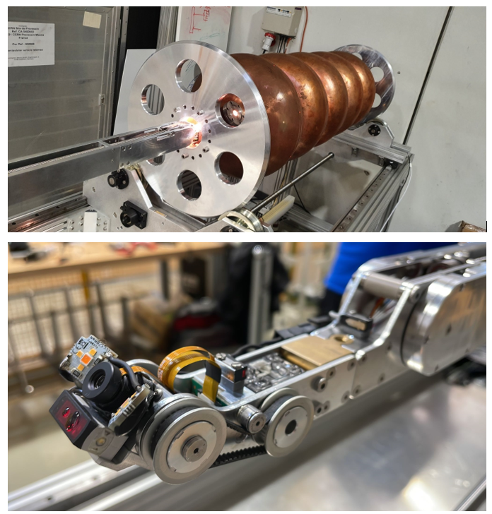
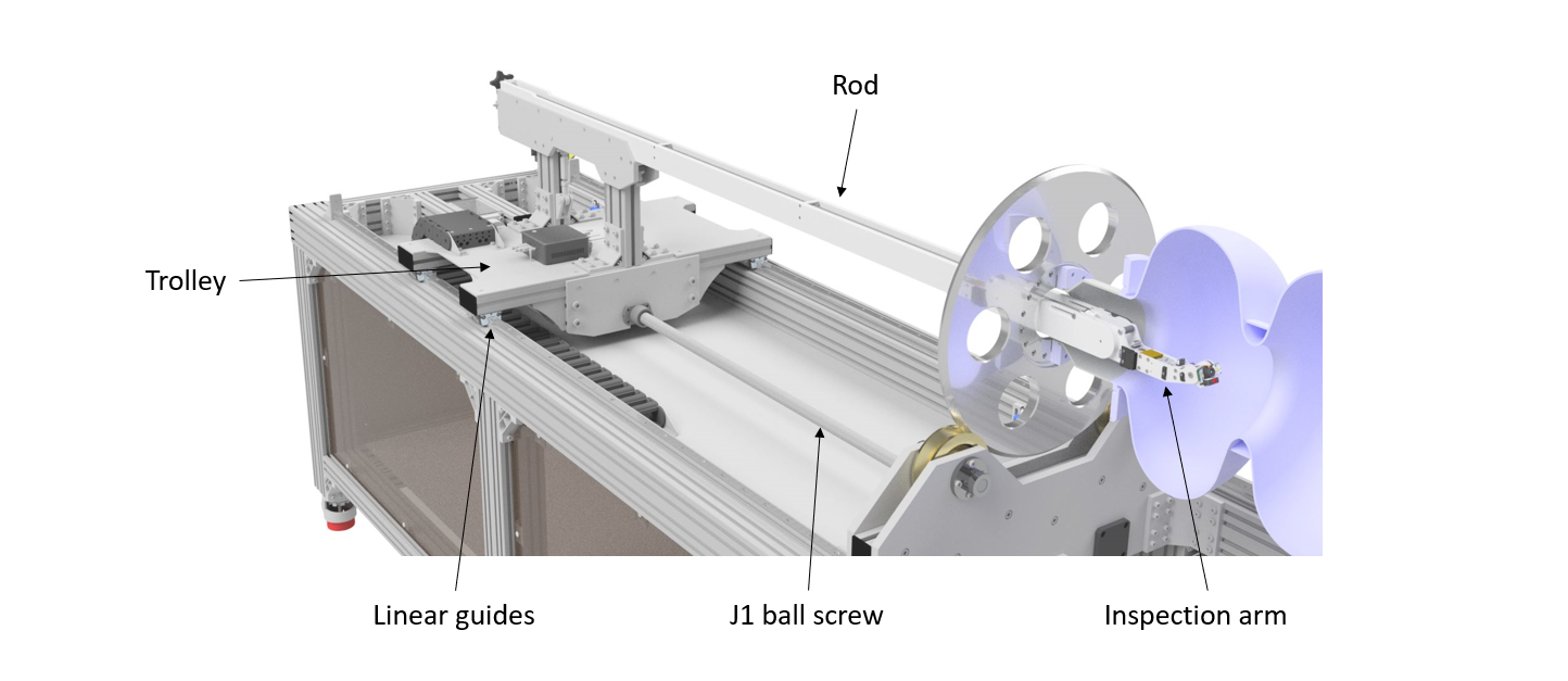
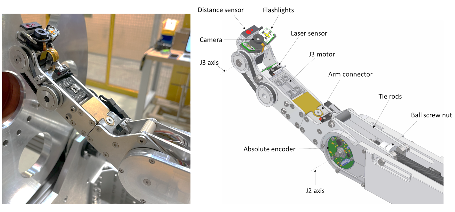
Inspection arm
The newly designed and built robotic inspection arm can enter inside the cavity by sliding (first joint) along its rotation axis, which is supported by an aluminum rod fixed to the trolley. The trolley, driven by a ball screw, moves on two linear guides.
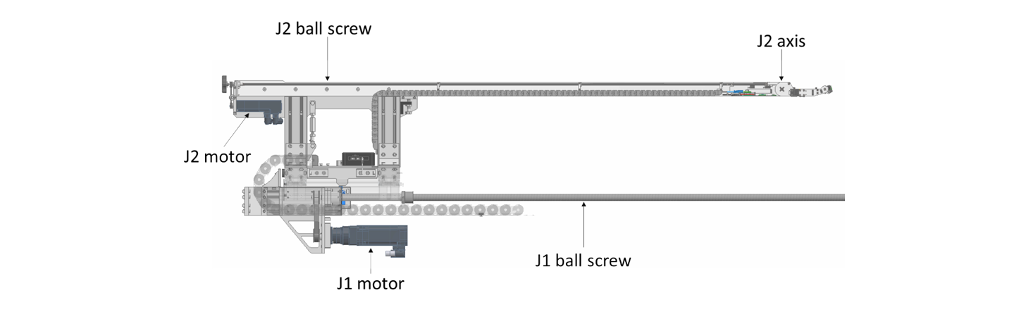
The second joint is located on the tip of the aluminum rod. It is driven by a second ball screw and motor fixed on the rear part of the trolley.
The second joint is rotated by two tie rods connected to the ball screw nut and it is controlled by using an absolute encoder. The inspection arm is linked to the second joint by means of a conical shape connector.
The camera is installed on the tip of the arm and is rotated with a motor and a timing belt. Two LED flashlights are fixed on V-shape support fixed to the camera lens.
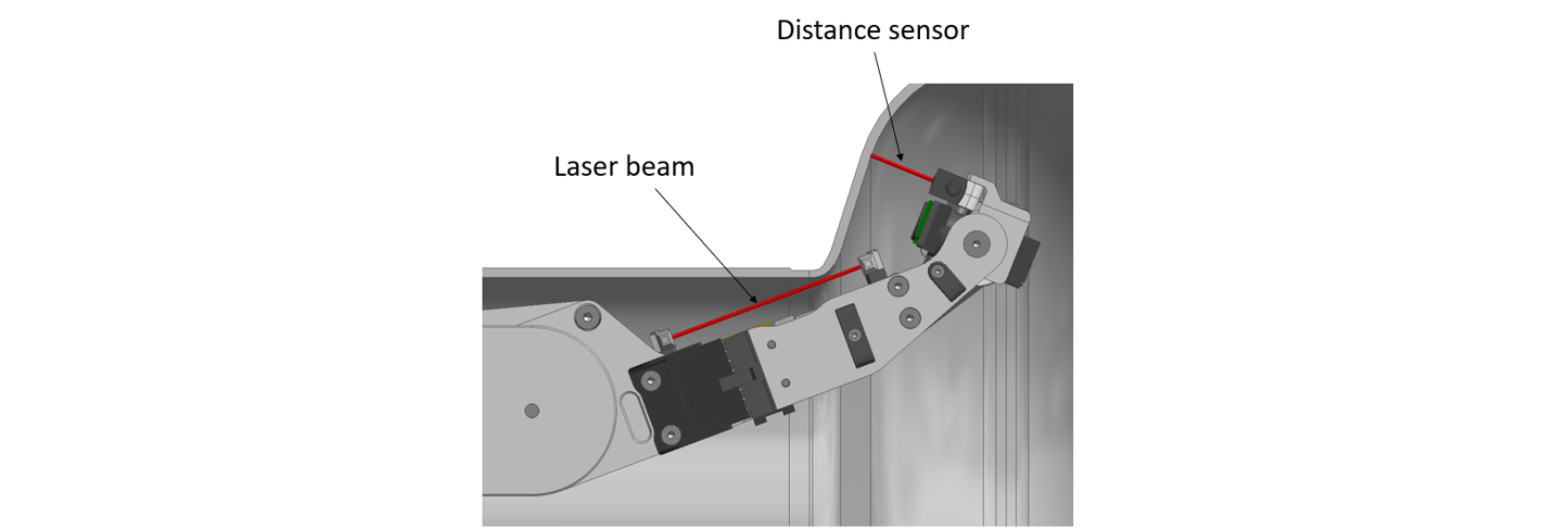
A distance sensor installed on the camera and two laser sensors on the top of the arm are used to avoid any collision with the cavity's inner surface.
Based on topology optimization studies, three different inspection arms were designed and developed, one for each cavity type, in order to be able to follow the inner surface at 23mm of distance:
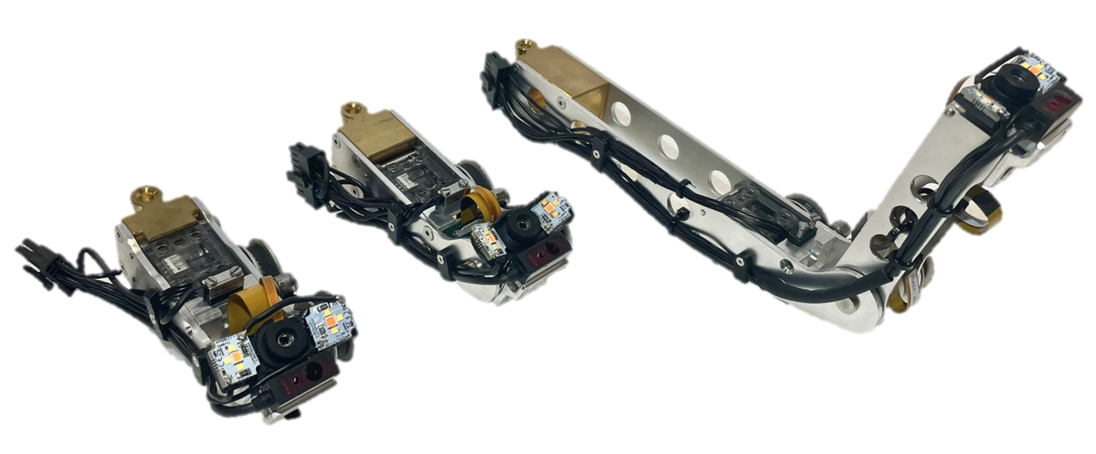
Each arm is designed to reach all the positions needed to scan the entire inner surface of the cavities.
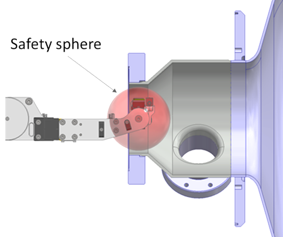
In case of system failure, the camera and the sensor at the tip are arranged to stay in a safe working space (Safety sphere) which allows the arm to be extracted through the inlet flange. This procedure is always possible since the two other motors that controls the motion of the arm are located outside of the cavity – not on each joint – meaning that in case of any motor’s failure, it is always possible to change the motor with a spare and retract the arm safely. To achieve the retraction, an emergency control algorithm allows recovering the arm without colliding the cavity.
Trajectory Generation
Trajectory of the robotic arm of ARIS (Video: CERN).
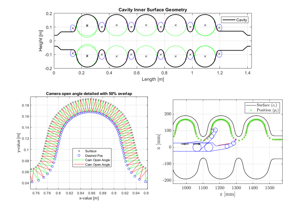
The trajectory of the robotic arm is computed in two steps. Firstly, the inner surface is reconstructed based on the 2D industrial drawings of the cavity. Then, each position of the robotic arm can be computed while respecting three main constraints (derived from the main requirements previously mentioned):
- The camera must always be perpendicular to the surface
- Each photo taken has to have 30% of overlap between each other
- Keeping the constant distance to the surface of 23mm
Anticollision System
To safely scan a cavity without colliding it, the arm is equipped with one distance laser located below the camera and one laser beam located at the main arm's length. The system stops immediately if either the distance measured from the first laser is smaller than a given threshold or if the laser beam is interrupted.
Imaging systems
The newly vision system is composed of three main components:
- A liquid lens: it allows to overcome depth of field (DOF) limitations by allowing the focus to be electronically adjusted without requiring any mechanical movement. This technology is perfect for this application since the curvature of the cavity creates some DOF problems.
- A high-resolution miniature camera: This 18Mpix miniature (15x15x8 mm) camera takes pictures of sizes around 12x16 mm which allows a high resolution on the surface quality. Its size makes it compact and easy to integrate.
- LED flashing system: Two LEDs of 314 lumens each are fixed near the camera objective and are triggered each time a photo is taken for a variable exposure time which is between [0.5 – 1.5] ms.
Full scan procedure
A full scan procedure is divided into stripe scans. The system goes through each camera position computed. Once it has reached one, it stops, and the cavity starts to turn around its beam axis and the camera starts to take photos by triggering the LEDs. Once the revolution is complete, the photo stripe of this position is done, and the system can move to the next position. By iterating on each position, a full scan is completed, and the robotic arm is safely redrawn.
The full scan procedure of ARIS inside the cavity (Video: CERN).
Main challenge of ARIS: perform a full scan inside RF cavities, by ensuring the overlap percentage (Video: CERN).
The acquisition’s frequency and the cavity angular speed are determined based on the cavity tangential velocity and the current radius of the cavity. An autofocus algorithm is running during the acquisition to always keep the Region of Interest (ROI) in focus.
Currently, several full scans have been performed and the results are promising. Below, some relevant metrics are shown:
- 1 picture
 50MB
50MB - Full cavity scan 20’000 pictures
- Full cavity scan 1 TB of storage
- Full scan time for a 704 MHZ 5-cells cavity = 12 hours
Human safe system
Besides the system components mentioned above, two safety laser scanners are fixed on two opposite edges of the structure, and they are connected to a PLC. They guarantee the human safety, by triggering the shutdown of all the system, if somebody approaches too close to the system.
System User Features
The final user of the system will be able to perform three different scan modes through a user interface currently in development:
- Full scan, which allows to scan the entire cavity
- Partial scan, which inspects only a given area, by either specifying the region or selecting two old photos
- Manual mode, which allow to reach any point of the cavity inner surface, by either selecting a position or an old photo. Then the user will be able to manually tune the camera settings and take pictures.