SAMbuCa: From Redesign to LS3 Deployment
BE-CEM is developing the high-performance field Sensors Acquisition and Motion Control system (SAMbuCa), with the purpose of consolidating the sensor, actuator and driving electronics requirements of the different motion control systems at CERN.
The system, which is set to be deployed during LS3, will be used for the LHC collimators, North Area targets, UA9 collimation (LHC and SPS) and scrapers, as well as for the HL-LHC Full Remote Alignment System (FRAS). The above list is non-exhaustive as the SAMbuCa system has also attracted the attention of other groups at CERN.
Initially foreseen to be based on a combination of the PXIe and DI/OT platforms, the SAMbuCa system has undergone a significant redesign in the past 1.5 years, resulting in a purely DI/OT-based solution. This redesign has been driven by the need to address several shortcomings of the initial design, in particular related to thermal dissipation issues and complicated (and very expensive) cabling.
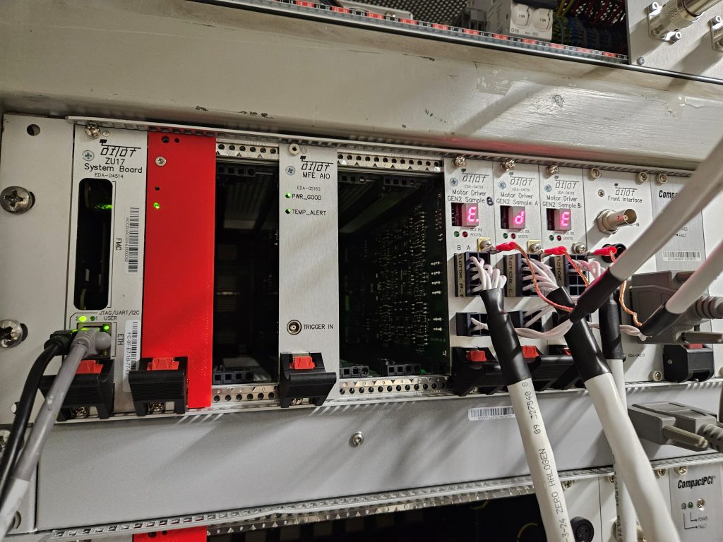
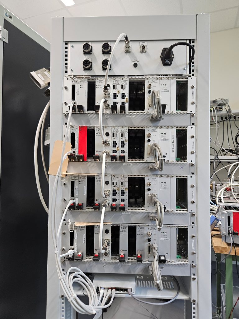
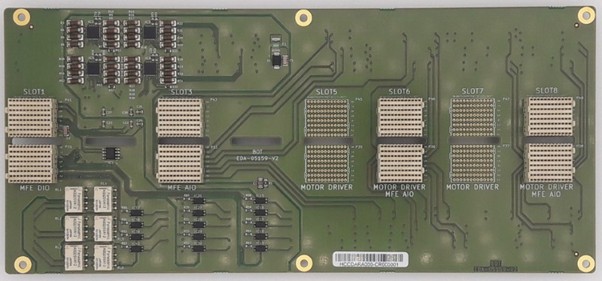
The new DI/OT-based design provides an elegant solution where a single DI/OT crate is capable of controlling up to 8 (possibly 10 in the near future) motor axes, read out position sensors (resolvers, LVDTs, etc.), interface with limit switches and other similar digital input devices (32 industrial input channels available) and drive 32 isolated digital outputs for controlling external motor drivers or any other device. The SAMbuCa system also provides 6 relay outputs (mostly aimed at interlocks).
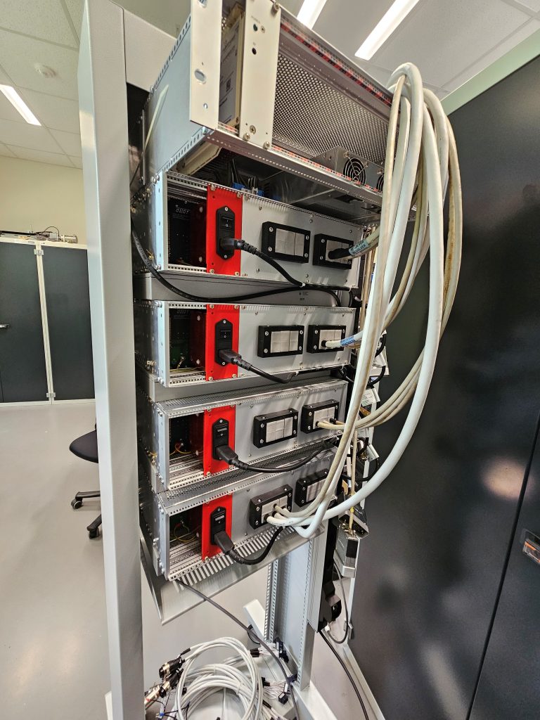
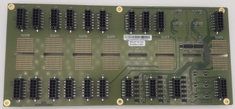
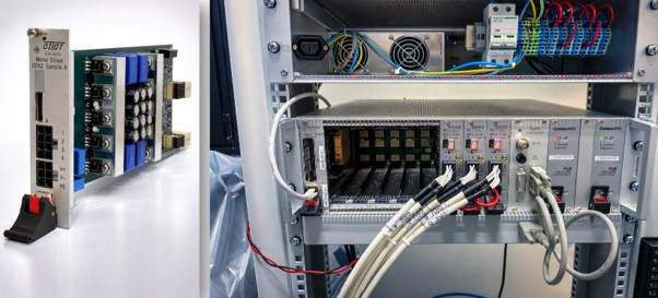
The system uses a specially designed Rear Transition Module (RTM) which allows us to shorten the depth of the DI/OT crate while having all the cabling for the analogue and digital I/O coming off the back of the crate. Thanks to the shortened crate, the SAMbuCa system occupies half the depth of a standard rack, allowing deployments in shallow racks (or racks where equipment is mounted on both sides).
All the control is performed by the Xilinx Ultrascale+ FPGA on the DI/OT system board, using a combination of Linux (CERN FECOS for arm64, including FESA support), bare-metal software and programmable logic. The FPGA provides four ARM CPUs, two dedicated to Linux and two to bare-metal software, enabling hard real-time control alongside the Linux environment.
To be able to achieve this partitioning of processing and memory resources, the SAMbuCa development team implemented a solution based on the Xen hypervisor. Following the successful validation of this approach, BE-CEM is now exploring the integration of Xen as an option in the upstream DI/OT build system, in order to make it available to other DI/OT-based systems.
Motor Control
Stepper motor control requires a dedicated power output stage, commonly referred to as a motor driver. Commercial motor drivers often exhibit degraded performance when motors are connected through very long cables. In such configurations, impedance mismatches between the motor and the cable can generate signal reflections. These reflections may interfere with the current regulation circuitry, reducing control stability and overall performance. To address this limitation, a custom electronic board known as the Gen2 Motor Driver has been developed for SAMbuCa and is currently fully integrated into the DI/OT ecosystem. The board is based on a Texas Instruments microcontroller integrating a wide range of peripherals, including sigma-delta modulators, ADCs, DACs, UART, SPI, I²C interfaces, and PWM generators. The driver is capable of automatically identifying the characteristics of the motor-cable system and determining suitable PID controller parameters, avoiding the need for manual tuning. Step commands are implemented through dedicated hardware signals, which can be routed either through the DI/OT backplane to the system board or through the Rear Transition Module connector. Configuration and monitoring of driver parameters are performed via UART interfaces, which are accessible either from the system board or through the Rear Transition Module of the DI/OT. Finally, an SPI connection to the system board enables the transfer of position sensor data, for example from a resolver to the driver. This allows the implementation of closed-loop motor control.
Reliability and Production Testing
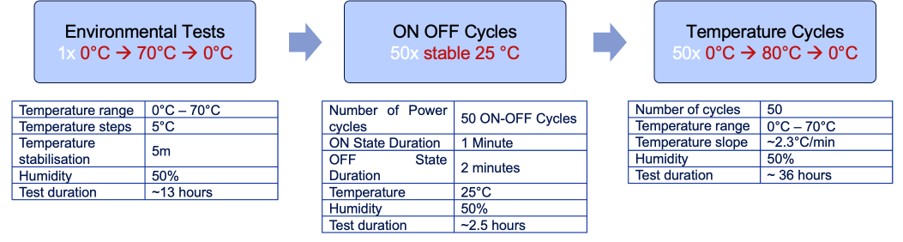
Before any SAMbuCa board enters series production and operational deployment, it must be proven to perform correctly not just on the bench but across the full range of conditions it will face in the field. Reliability tests expose each board to environmental, power-cycling and thermal-cycling stress, revealing temperature-dependent drift, marginal designs and failure modes that can be difficult to detect during nominal testing. Once the cards have been validated, the Production Test Suite (PTS) then turns this understanding into a repeatable, automated acceptance procedure with full requirement coverage, so that every manufactured unit is validated to the same objective standard. Together they catch defects early and give confidence that the hardware will operate reliably over its lifetime. Currently the Reliability and Production Test Systems (PTS) for the SAMbuCa boards are at different stages of maturity, ranging from fully implemented test suites to campaigns under validation. At the moment, the peripheral cards: temperature reading (RTD), Digital IOs, Analog IOs and Motor driver are being tested in the climatic chambers and are yielding promising results.
AIO and DIO peripheral Board reliability tests
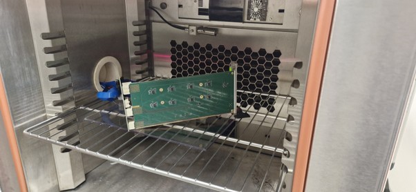
The reliability tests for the AIO V2 board have been completed, characterizing the analogue-to-digital performance through the standard dynamic figures such as ENOB, SINAD, SNR, THD and SFDR evaluated at a 1 kHz input. A dedicated gateware running at 50 MHz was developed so that the boards could be ported out of the DIO chassis and tested in the oven, thereby isolating the tests to impact only the board itself. The latest results are very good, with an average ENOB of 14.941 bits. The board is now being prepared to finalize testing the DAC.
Gen2 Motor Driver
The FlexDrive motor driver PTS is ready for delivery. Currently a pre-series sample has just completed a full cycle of Acceptance and Reliability Test Campaign, executing 33 individual tests and the results are being analysed.
Flex Drive test cycles
The complete system has been successfully functionally tested through cycling tests on a single collimator testbench in B927.
Another test setup for three collimators is also being prepared in B272. Looking further ahead, we are aiming for test deployments in FRAS (RAC3 and IT String) in Q4 2026.