
CHARMbot enables remote board exchange at CHARM
Successfully trialled at CERN’s CHARM irradiation facility, a new robotic board exchange system enables remote replacement of test boards, reducing the need for personnel access and making radiation testing more flexible.
The EPR section’s Radiation Test Service uses CERN’s CHARM facility to qualify electronic boards and components for accelerator equipment exposed to radiation. The MRO section, in collaboration with EPR, has adapted CHARMbot and designed, produced and installed a dedicated robotic test station that enables test boards to be inserted and removed remotely, without requiring personnel to enter the irradiation area. Building on CHARMbot’s existing role in visual inspections at CHARM, MRO has equipped the robot with a dedicated interface that enables it to connect to the test station, exchange test boards and transport them between the irradiation area and a designated exchange point in a radiation-safe area (Figure 1).
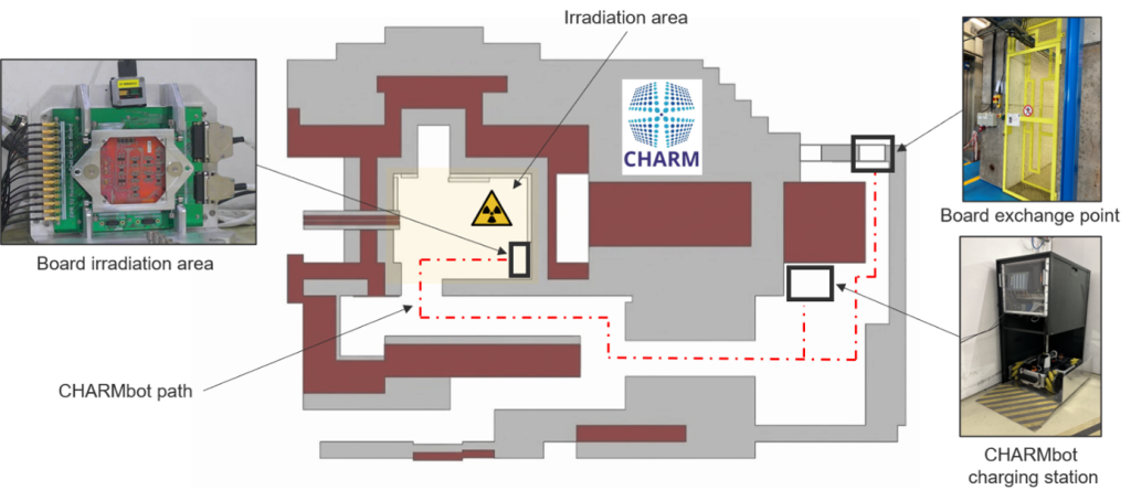
When a board reaches its target radiation dose, the robot can remove it from the irradiation area and transport it to the exchange point, where personnel can safely retrieve it and load a new board onto the robot. Boards can also be exchanged in the event of a test failure. This capability allows irradiation campaigns to continue with minimal interruption, improving the use of available beam time and giving the test team greater flexibility throughout the week.
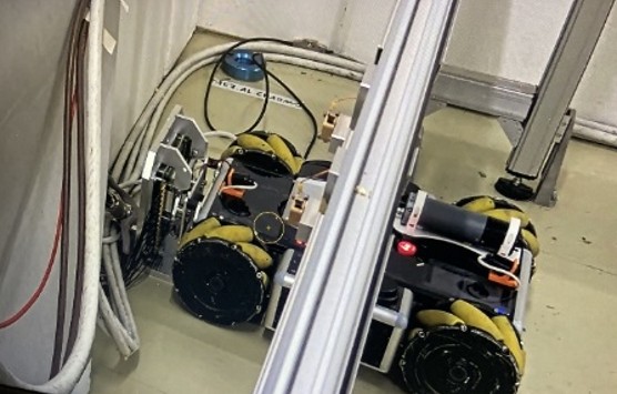
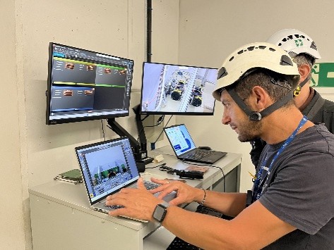
The PCB exchange system comprises a carrier board station and a daughterboard frame. The frame holds the test board and enables the robot to insert it into and remove it from the carrier board using a dedicated interface. The carrier board station is installed in the irradiation area and supports the carrier board, which powers and monitors the test board during irradiation. Four guide rollers assist with the initial positioning of the robot, while dedicated locators ensure precise alignment of the test board with the carrier board’s pins and connectors (Figure 3).
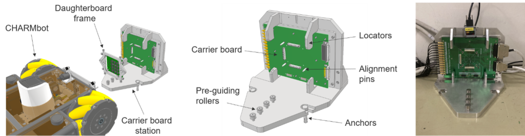
The daughterboard frame provides the mechanical interfaces required for precise remote insertion and removal of the test board. Pre-alignment rollers run along the station’s locators to guide the board into position, while dedicated locating-pin holes and electromagnet contact pads enable CHARMbot to securely engage and release the frame (Figure 4).
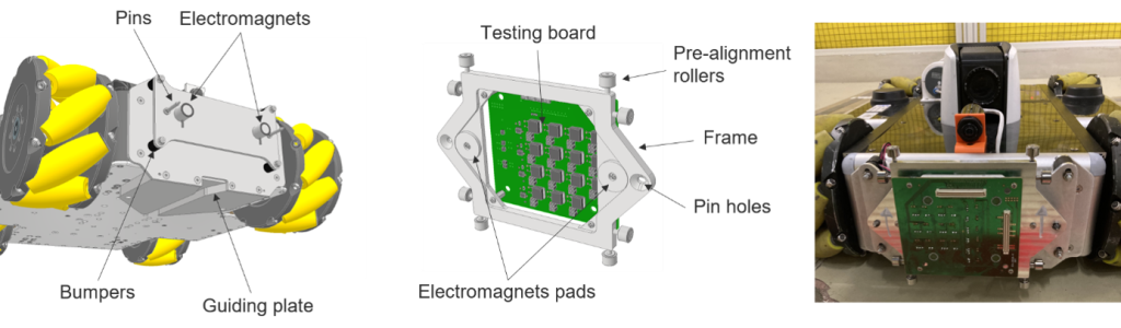
A dedicated robot interface (Figure 4) was also developed to enable CHARMbot to perform board exchanges. It incorporates alignment pins and electromagnets to engage and release the daughterboard frame, four bumpers to cushion contact caused by misalignment or impacts during manoeuvres, and a grooved guide plate that engages with the station’s guide rollers to align the robot with the carrier board station.
How does the system work?
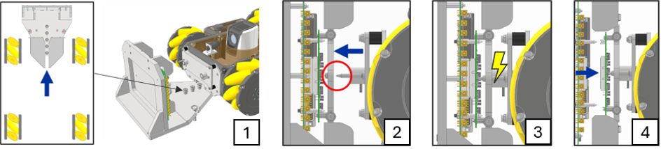
Before the irradiation campaign begins, the test board is mounted in the daughterboard frame and connected to the carrier board at the test station. When the board needs to be replaced, CHARMbot leaves its charging station and approaches the test station to begin the disconnection procedure.
As the robot advances, the station’s guide rollers engage with the grooved guide plate, aligning the robot with the daughterboard frame (1). The robot moves forward until its alignment pins enter the corresponding holes in the frame (2) and the electromagnets contact the frame’s pads (3). The operator then activates the electromagnets to secure the frame and reverses the robot, withdrawing the frame and disconnecting the test board from the carrier board (4).
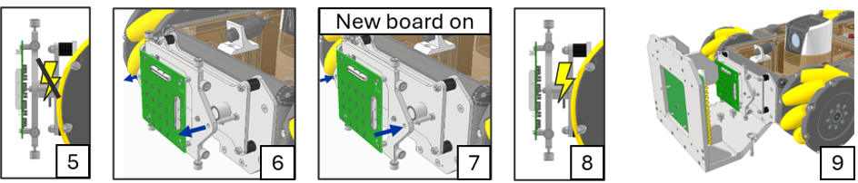
The robot carries the board to the exchange point, where the operator releases the electromagnets (5) and manually swaps the frame and the board with a new one (6)(7) and switches the magnets on (8).
The robot then returns toward the irradiation area. As it approaches and self-aligns with the carrier board station (9), the rollers on the frame engage the locators (10) and guide the pin engagement (11). The robot pushes the board forward until the connectors are fully plugged in (12). Finally, the operator remotely verifies that the test board is correctly connected, releases the electromagnets (13), and moves the robot back to the charging station.

The system was designed in accordance with the CERN Code of Practice for Robotics-Assisted Maintenance (COOPERATE) and deployed at CHARM for an initial three-week trial. During this period, several cryogenic-system boards were successfully irradiated to their target doses. The trial demonstrated how robotic board exchange can improve the flexibility and efficiency of radiation testing at CHARM while reducing the need for personnel to enter the irradiation area.
Beyond board exchange, this application at CHARM provides a foundation for a broader approach to robotic maintenance in accelerator facilities. With suitable adaptations, the same principles could support tasks such as exchanging cards in electronics racks, replacing faulty modules, and maintaining electronic systems in areas where radiation or access constraints make human intervention challenging.
The longer-term vision is to design equipment and robotic interfaces together, making remote maintenance an integral part of future accelerator infrastructure. This approach could be particularly valuable for projects such as the Future Circular Collider (FCC), where incorporating robotic maintenance from the outset could improve accessibility, maintainability, and operational availability. Building on the experience gained at CHARM, increasingly autonomous interventions could reduce personnel exposure and help restore equipment to service more quickly, paving the way towards more maintainable and robot-ready facilities.